Because I live in a flat I have never had a brilliant antenna, the best I could muster is a folded dipole on the 20M band and a magnetic loop on 40M. I have always liked digital modes and like to participate in RTTY contesting, of course I do not do very well but that’s not the point. Anyhow because of the new regulations and with an antenna just a couple of metres from my head I cannot run much power and to be honest, its quite fun to see how far I can get using just 20 to 30 watts.
Whats this all got to do with a HWEF antenna I hear you ask, well that’s quite simple im thinking about going portable and an end fed antenna looks like a good choice
So the search began on the internet and the following journey started.
The 49:1 Impedance matching UNUN
First mistake buying a hookie QRP guys EFHW on eBay just avoid the temptation
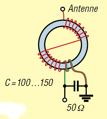
Second build my own, this lead me to the usual suspects a 49:1 matching transformer wound 2 / 14 as in diagram below I built a transformer using this design using a FT140-43 and it measured fine, but after further searching on the web I decide to change direction slightly
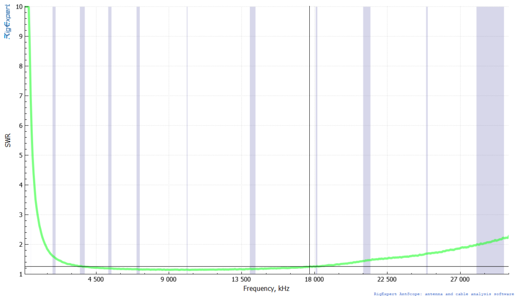
After watching Colin MM0OPX youtube video https://www.youtube.com/watch?v=nZ-G4hJCTSM I decided to re-wind to a 3 / 21 close wound design as the efficiency is higher, this measured very well into a resistive load as you can see in plot below
So now with the matching transformer made, I fitted it all into a box and superglued it shut to keep it waterproof
But the fun doesn’t stop there oh no, the rabbit hole of constructing the antenna began
First was a 10M pole, I searched around on Amazon and eBay looking at endless roach poles and flag poles until eventually I came across a 10M fibreglass flagpole with a 20\% eBay weekend deal costing me £33.00
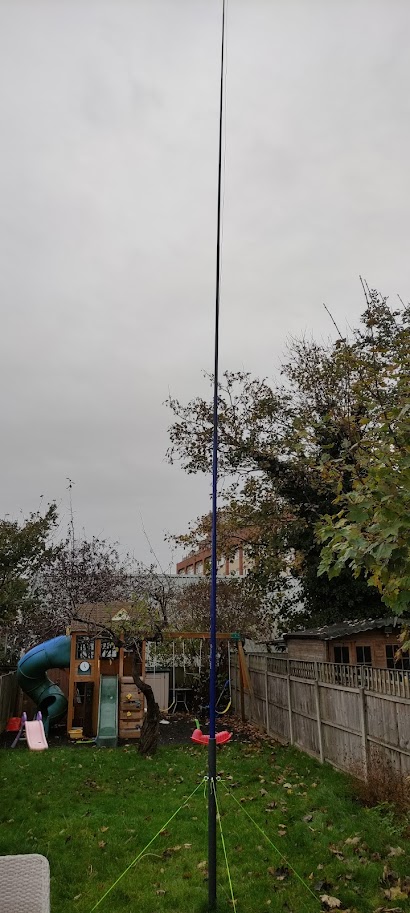
My thoughts then were to how to secure the pole to the ground, and I came up with the idea to have short piece of pipe that can be guy roped to the ground using cord and tent poles. I knew the pipe would need to be strong so after a great deal of searching I found piping suitable for pressures up to 10 Bar, this had an outside diameter of 63mm and inside diameter of 57 mm making the walls 3mm thick. I had to buy 2 pieces at 1.25M a piece which cost £18 inc delivery so the cost of the aerial begins to rise.
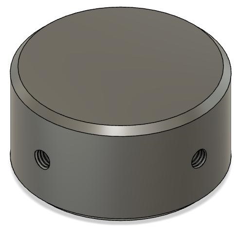
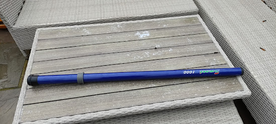
By shear fluke the bottom of the flagpole had a screw cap that fits snugly into the pipe so all that was required was a bung to stop the pole falling all the way down the pipe and a reducer so that the flagpole was held firmly in place at the top of the pipe, the bung could be held into place with 4 eye bolts to secure the guy ropes so I designed some parts in Fusion 360 and sent the STL files to a friend to slice and print them.
The bung was made with 4 screw threads to fit M6 eye bolts see image below
And then the reducer
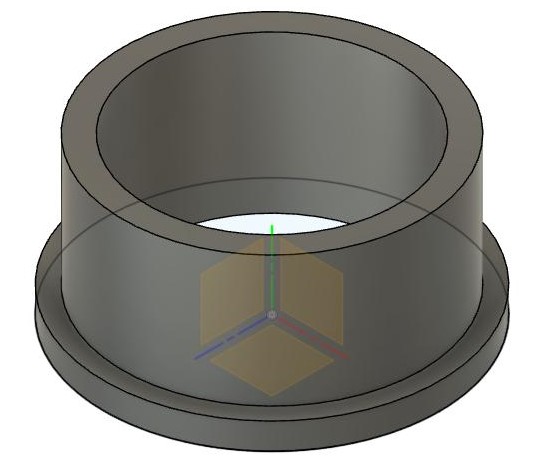
Picture below showing the spacer fitted to the telescopic mast
Then the drainage pipe fitted with the 4 fixings that are screwed into the 3 D printed bung
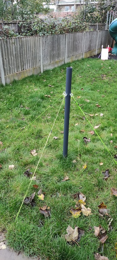
Now the telescopic mast fitted into the drainage pipe
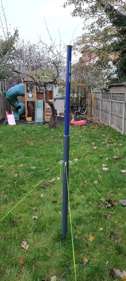
Now fully extended
