I purchased a couple of the UK5V handhelds, well at 14 quid each they are great for messing around with even if its only to change the firmware. Their harmonic output is well documented on the internet and I would like to use them on transmit without getting into trouble so thought I would make a low pass filter. So I started by using the online calculator at https://markimicrowave.com/technical-resources/tools/lc-filter-design-tool/ I ran the parameters through for a 150Mhz 5th Order Chebyshev filter and was given the following circuit

Its a starting point, but I didn’t have an LCR meter at the time so decided to use another online calculator to work out the correct winding for the inductors. This led me to https://m0ukd.com/calculators/air-cored-inductor-calculator/ cut a long story short I made a major cock up and turned two coils with a 5.5mm ID with a 0.8 Cu wire which were too inductive. I then made a prototype board up and tested and if I was thinking of making a 70Mhz LPF then I would have nailed it. This didn’t phase me at all… honest!! but the initial disappointment did bring a great idea of halving the inductances, I say great because as it turns out it was an absolute fluke of an idea and the resulting HPF although not perfect definitely ticked all the boxes of the job it is required to do, and if its not broke don’t fix it.
To recap and to save anyone looking further the only modification to the above circuit was to cut the chokes to 3 Turns of 0.8mm enamel copper wire on a 5.5mm drill bit. If you are interested in the nitty gritty then read on.
The Build
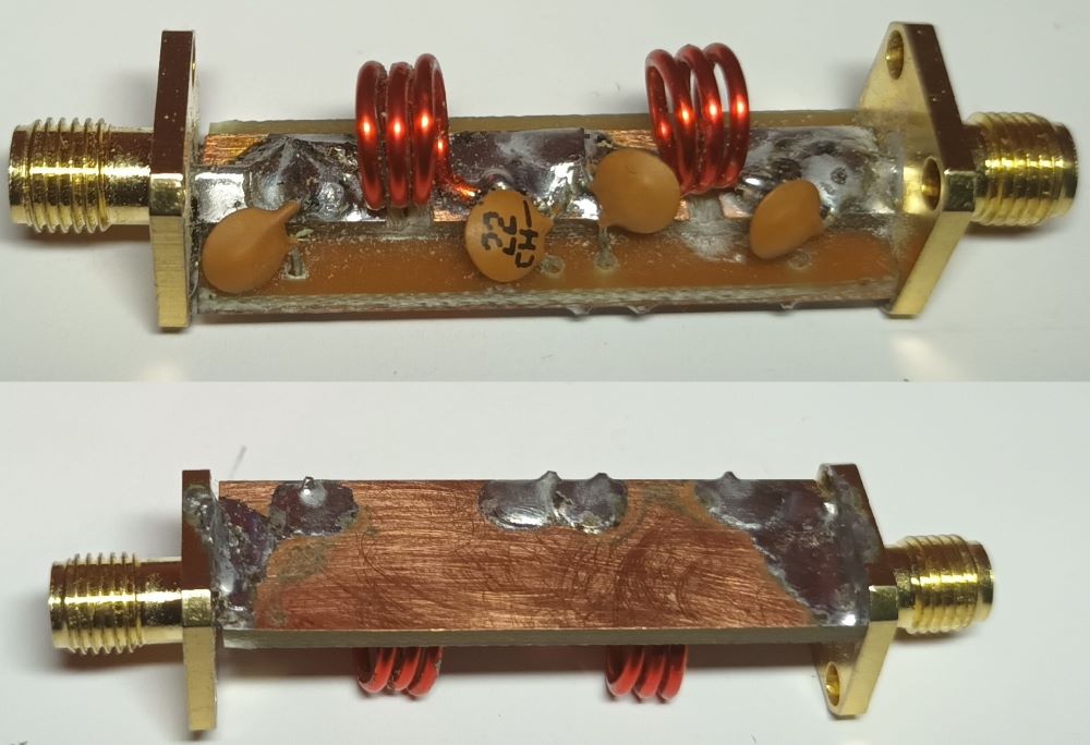
The connectors I used were SMA Female bulkhead type which I found on good old AliExpress https://a.aliexpress.com/_EG4sqI7 I chose this type as the they allow me get the PCB flush to the metal housing to solder direct to the ground of the PCB (You’ll see what I mean later)
Not having any way of making a proper PCB the only route to take was to use some single sided copper clad board I had available. I cut this into 2 pieces one the thickness of the SMA connector so 12.5 x 38mm and a strip at 6 x 38mm. These were then superglued firbreglass side to fibreglass side so effectively you have a double sided board. Once stuck together I used a dremmel to score two lines in the top strip so there were three isolated pads.
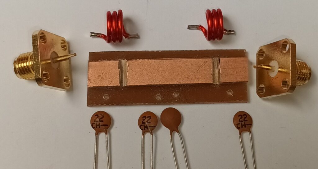
All the parts made and ready it was just a few minutes and the whole filter was soldered together
Testing
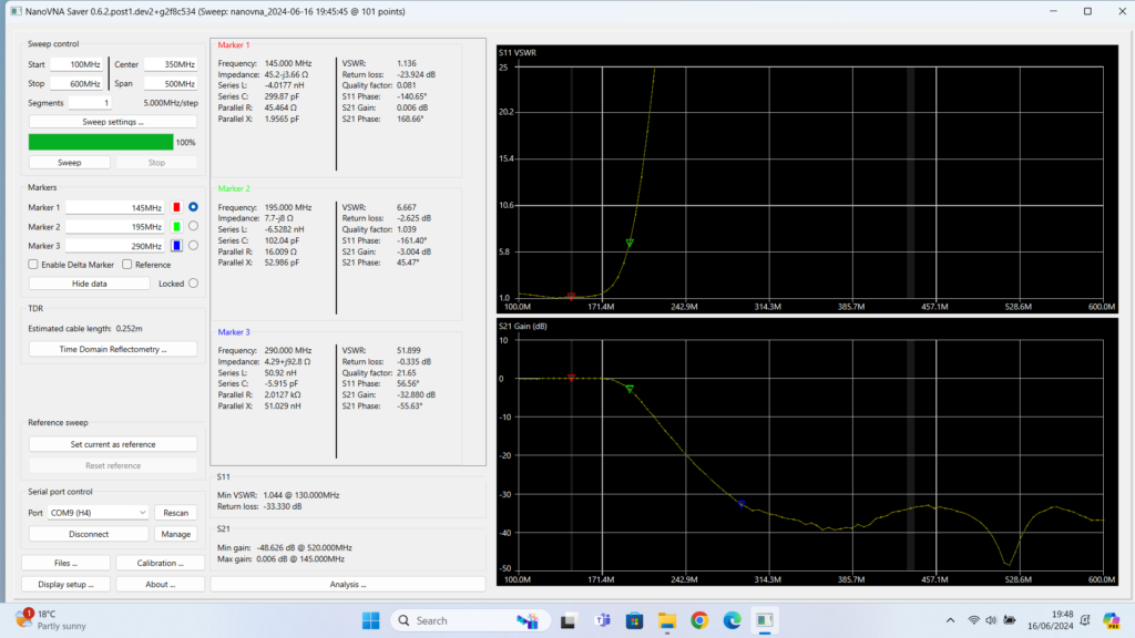
I tested using a Tiny SA Ultra, the crossover point was a little higher than I would have liked but the insertion loss was extremely low and the VSWR very good on 2M, it had about 35dB of attenuation on around the second harmonic of 2M so was more than enough to tame the UK5V
UK5V Unfiltered
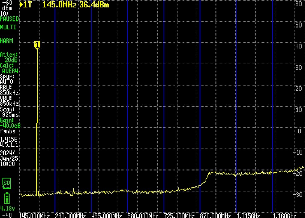
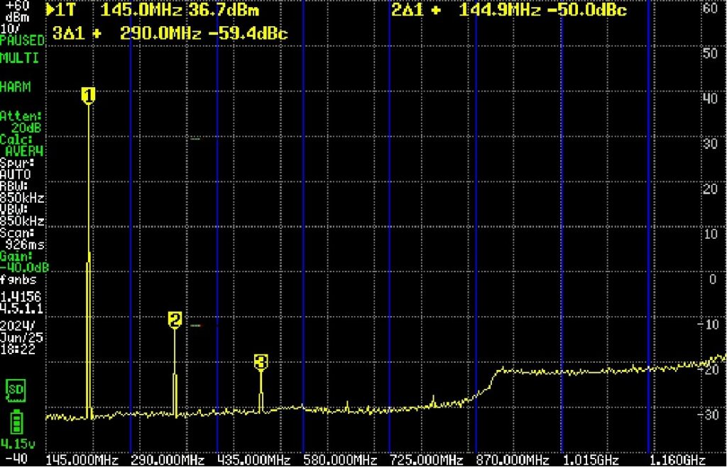
Using a Tiny SA Ultra I checked for harmonics at 145 Mhz into a 50 Ohm dummy loadusing the harmonics function. The below images shows the result
UK5V Filtered
Performing the same test but this time with the LPF fitted
